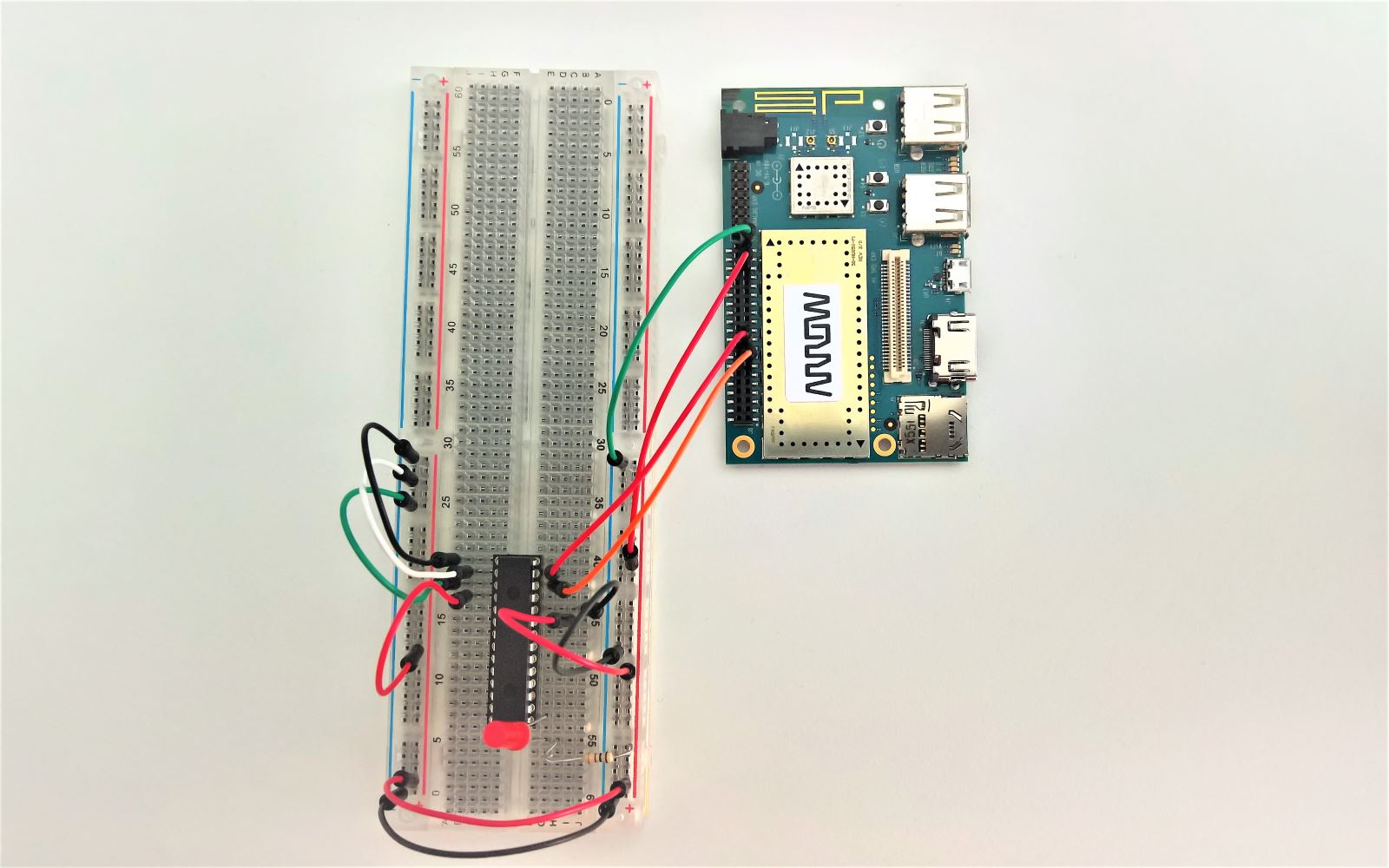
MCP23017-E/SP with DragonBoard 410c on Windows 10 IoT Core

The last few days I was trying to add additional GPIO ports to a DragonBoard 410c running Windows 10 IoT Core. I chose a MCP23017-E/SP chip that will provide you with 16 extra GPIO pins through I2C. Getting it to work is actually not that hard, if you can (unlike me) avoid those few nasty pitfalls.

Wiring MCP23017-E/SP & DragonBoard 410c

[fusion_builder_container hundred_percent=”yes” overflow=”visible”][fusion_builder_row][fusion_builder_column type=”1_1″ background_position=”left top” background_color=”” border_size=”” border_color=”” border_style=”solid” spacing=”yes” background_image=”” background_repeat=”no-repeat” padding=”” margin_top=”0px” margin_bottom=”0px” class=”” id=”” animation_type=”” animation_speed=”0.3″ animation_direction=”left” hide_on_mobile=”no” center_content=”no” min_height=”none”]

DragonBoard 410 & MCP23107 Pin Mappings
DragonBoard 410c Pin Mappings | more Info

Wiring up the port expander is fairly straight-forward, especially if you only want to add one chip:

  • Connect the SCL (12) pin to the DragonBoard I2C0 SCL (15) pin
  • Connect the SDA (13) pin to the DragonBoard SDA (17) pin
  • Connect RESET (18) and VDD (9) to the DragonBoard 1.8V PWR (35) pin
  • Connect A0, A1, A2 (15, 16, 17) and VSS (10) to Ground / GND (1, 2, 39 or 40)

DragonBoard 410c & MCP23017 Breadboard Wiring
I bought a few MCP23017 chips with sockets from Amazon. Those sockets unfortunately did not connect properly to my breadboard. After upgrading them to proper ones (like these, notice the round pins) I had no more connection issues.

Connecting to MCP23017-E/SP through I2C on Windows 10 IoT Core

The “Windows.Devices.I2c” namespace does most of the work for you when trying to talk to an I2C-connected device. There’s an official code sample on how to do that. There are a few things to keep in mind, though.

Most (if not all) tutorials for I2C on Windows 10 IoT refer to a RaspberryPi (2/3) setup. There, you’ll be using the 3.3V power source for your chip. However, the DragonBoard will only work with the 1.8V pin. That’s not that big of an issue as the MCP23017-chip will work with 1.8V – 5.5V.

BUT:

You can’t use I2cBusSpeed.FastMode (aka 400kHz) at that voltage level with the expander chip. You’ll need to switch to I2CBusSpeed.StandardMode (100 kHz), otherwise you’ll get the dreaded “Slave address was not acknowledged.” error, which can basically mean anything.

Those are two days I won’t ever get back…

Another thing I was uncertain about was the I2C address of the port expander. I seems you’ll only need 7-bit without the r/w-bit, so you get 0x20 with all address ports (a0, a1, a2) set to ground.

Working with MCP23017

When looking at how to actually work with the GPIOs on the expander chip I found a great helper class for the Raspberry Pi written by Michael Hacker (awesome name for a programmer btw.) that I was able to adapt for the DragonBoard. This will take care of a lot initialization work as well as give you nice enums & constants to work with the GPIO pins instead of reading and writing meaningless hex-codes.

This way turning off and on an LED light at GPB0 can be done in these few lines of code:

private MCP23017 i2cPortExpanderClient = new MCP23017("I2C0");
await i2cPortExpanderClient.Init();
i2cPortExpanderClient.SetDriveMode(MCP23017.Pin.GPB0, MCP23017.PinMode.Ouput);
i2cPortExpanderClient.Write(MCP23017.Pin.GPB0, MCP23017.PinValue.High);
i2cPortExpanderClient.Write(MCP23017.Pin.GPB0, MCP23017.PinValue.Low);

[/fusion_builder_column][/fusion_builder_row][/fusion_builder_container]

Leave a Reply

This site uses Akismet to reduce spam. Learn how your comment data is processed.